I have been looking into how to show generalization when modelling a database using Crows Feet notation and came into some difficultly. Generalization in terms of a database is when one table has all of the fields of another table. Another way of explaining would be saying one table is extended from another. For example the tables Supervisor and SalesAssistant both contain all of the fields in the Employee table. How this is actually implemented in the database is another story, at the entity relationship modelling stage we are just defining relationships between tables and generalization is just one form of possible relationship.
So I have found three ways of modelling this relationship in Crow’s Feet which left me rather bambuzzled as to which one I should actually use. I will now show the three methods I have found.
Method 1
Any UML(Unified Modelling Language) modelers will know this notation as it is exactly the same. An non filled arrow is placed with the point touching the ‘superclass’ object and all classes that inherit from this class(subclass) are linked to this arrow by a black line. This is the same notation as used when doing any modelling in UML.
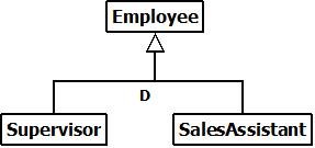
UML Notation can also be used in Crow’s Feet for Generalization with a slight difference in defining Participation and Carndinality.
Method 2
The second method is mentioned in a few text books and is rather neat and represents literally what the relationship describes. A large rectangle showing the name of the superclass is drawn. Within that rectangle any subclasses will appear. This shows that the subclasses are a type of the superclass and are in effect encapsulated which is the desired outcome at this modelling stage. Other relationships can either link to the subclasses or the superclass.
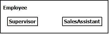
Box in box notation for ER diagramming using Crow’s Feet
Method 3
The third method is similar to UML again however the arrow and text is replaced with an icon that indicates the relationships completeness and disjointness.
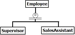
Like UML except without the arrowhead and with a symbol to indicate participation and cardinality.
All of these method are valid in a Crow’s Feet diagram because in the early days of this notation, people developed their own extensions to the notation. UML was created to avoid this by providing a standard of modelling for everyone to follow and that everyone can understand. Of these methods my favorite is the box in box method as it is neat and adequately models the actual relationship. However there seem to be limited documentation about this, Textbooks state this is how it should be used but don’t show how to model the participation and cardinality constraints. I would suggest a UML based notation to show the constraints.
Next blog post will be about my introduction to making a Single Page Web App using Ajax, Javascript and jQuery.
Andrew

Hi all,
We have been looking at Crows Feet Notation in my Advanced Database Systems module. I think that Crows Feet notation is a great notation to use as it uses minimal room and is easy to read. Its array of participation and cardinality symbols provide clear and understandable notation to understand what the diagram is modelling.

Notation for a Mandatory One Relationship Notation for a Optional One Relationship
 Notation for a Mandatory Many Relationship
 Notation for a Optional Many Relationship
In the diagram these will be double ended to show the relationship between two entities like shown in the example below.

Simple Diagram showing the relationship between Student & Result and Module & Result
The tool I use for ER Modelling using Crows Feet Notation is Dia. Dia is a german diagramming tool that supports all sorts of diagrams including cisco networks, flowcharts, chemical engineering , and electical. The applicaton started off its life in the linux enviroment as a gnome project. It has seen been ported into a windows version which is available at http://dia-installer.de/ . Dia also supports UML and Database diagramming. A basic ER diagram does not show attributes, it only show the relations between the entities. Below I show how to create the diagram above using Dia. First select the UML sheet from dropdown list that shows Assorted by default. Then select the first icon which contains a 3 tier box with xxx in the top line.

Dia UML Toolbox with Class Selected (blue background)
Click on the diagram space to the right to create a blank class. By default the class will have space for attributes and operations. To hide these right click on the object and select properties. Untick ‘Attributes visible’ and ‘Operations Visible’ and press OK.

Dia Class Properties Dialog Box (You also use this properties box to edit the entity name)
Right click the class and press copy, then paste into white area of the diagram. Repeat this action once more. Then rename using the properties dialog to create a the three classes Student, Module and Result.
Now use the generic line tool from the top toolbox (two green dots with a connecting black line) and draw a line from Student to Result. Right click the line created and select properties. You can use this dialog to set the symbols at each end. Set the start arrow to two straight lines and the end arrow to one straight line and three outreaching lines. To achieve this use the more arrows menu from the dropdown. I usally also alter the size to 0.9 * 0.7. You will need to unlink the two first by pressing the little chain icon. You should have the following in the properties window.

Completed relationship properties window
You now have a relationship between the two entities. Now create the second entity between result and module on your own.
Look out for my next post on how to show generalization when modelling using Crows Feet Notation.
Hi all,
Recently had an interesting lab session on using pipes as a method of communication between processes.
Pipes started off life on Unix systems as a way of transferring data between processes on the same machine. Pipes are now a method of IPC (Inter Process Communication).
Below I will show a very simple example of how to implement named pipes into a C# application.
First of create a console application in Visual Studio.
Then add a public method called ThreadStartServer to the program class generated by the IDE. The methods return type is void. Also create a public method again with no return type called ThreadStartClient. The client method takes one parameter called obj of type object
Inside the ThreadStartServer method paste the following code.
//Create a named pipe using the current process ID of this application
 using (NamedPipeServerStream pipeStream = new NamedPipeServerStream("PipeTo" + Process.GetCurrentProcess().Id.ToString()))
 {
 Console.WriteLine("[Server] Pipe Created, the current process ID is {0}", Process.GetCurrentProcess().Id.ToString());

//wait for a connection from another process
 pipeStream.WaitForConnection();
 Console.WriteLine("[Server] Pipe connection established");

using (StreamReader sr = new StreamReader(pipeStream))
 {
 string message;
 //wait for message to arrive from the pipe, when message arrive print date/time and the message to the console.
 while((message = sr.ReadLine()) != null)
 {
 Console.WriteLine("{0}: {1}", DateTime.Now, message);
 }
 }
 }
 Console.WriteLine("Connection lost");
Inside the ThreadStartClient method insert the following code
//Ensure that we only start the client after the server has created the pipe
 ManualResetEvent SyncClientServer = (ManualResetEvent) obj;
 Console.WriteLine("Please enter the process ID to connect to");
 string processIDToCall = Console.ReadLine();

//Only continue after the server is created
 using (NamedPipeClientStream pipeStream = new NamedPipeClientStream("PipeTo" + processIDToCall))
 {
 //The connect function will indefinately wait for the pipe to become available
 //If that is not acceptable specify a maximum waiting time (ms)
 pipeStream.Connect();

Console.WriteLine("[Client] Pipe Connection established");
 using (StreamWriter sw = new StreamWriter(pipeStream))
 {
 sw.AutoFlush = true;
 string message;
 Console.WriteLine("Please type a message and press [ENTER], or type 'quit' to exit the program");
 while((message = Console.ReadLine()) != null)
 {
 if (message == "quit")
 break;
 sw.WriteLine(message);
 }
 }
 }
Assuming your main class is called program, add the following code to the main method
Program reciever = new Program();
 Program sender = new Program();

Thread RecieverThread = new Thread(reciever.ThreadStartServer);
 Thread SenderThread = new Thread(sender.ThreadStartClient);

RecieverThread.Start();
 SenderThread.Start();
You can then run the application twice, once inside the debugger and visual studio and a second instance by navigating and executing the file created by the compiler. Following the instructions from the console will provide a basic messaging client between two processes on the same machine.
This application has shown how to create a unique named pipe which only has a single direction of travel. The pipe can send any message or object down the pipe to the interconnected process. In order to create bi-directional communication we have created another pipe going in the opposite direction. The method of joining the processes to each end of the pipes is straightforward. Careful management needs to be executed to provide a robust application when dealing with code that you are asking to wait for a message until it gets one. Luckily in this method if a pipes connection is lost then the application stops the waiting for a message without causing an exception. If this mechanism was not in place the application would have to be force-ably terminated to stop it waiting for a message from a no longer existent pipe.
Hi, My name is Andrew Belson. Currently I am studying BSc Software Development at Teesside University. I have created this blog as a way of documenting my progress during the final year, and sharing anything interesting, useful, emerging and just mental that I come across. So let me start with explaining the modules I will be studying this year.
Compulsory
Alternative Programming Approaches: This module will demonstrate that there are alternative ways to approach a problem than just using the same language all the time. Starting off with looking at the benefits of Erlang and what problems Erlang is best applied to, the module will then move on to look at Neural Networks, an Artificial Intelligence approach to problem solving using programming.
Software Architecture: This module will look at different ways of constructing software to get the most robust outcome with underlying theory of how software is layered and linked. What the IDE also automatically does and the implications of this are also covered.
Final Year Project: For this I will have to think of a project to undertake for 20 weeks, either a form of research report or a application which is called the ‘product’. Alongside this I have to create a report which supports my decisions and discusses why I have made the decisions I have, while also documenting my plan, progress and evaluation.
Optional
Rich Internet Applications: This module will start of with looking at the new emerging HTML5, CSS3 and JavaScript. This module will then cover how to make a SPA (Single Page Application) and using AJAX within our web applications. I have chose this module as the software world is changing and web applications are becoming so sophisticated. Many desktop applications can now work perfectly fine as a web application and this brings the added bonus of cross operating system compatibility and no lengthy install procedures using up space on a hard drive.
Advanced Database Systems: This module will cover Entity Relationship Modelling, Relational Algebra and OLAP(Online analytical processing). I chose this module because following from my very high score of 100% in the second year module Database Systems. Joined with the realization that there in no escaping from databases of varying formats, sizes and complexity; Which I gained from my year in industry programming for DuPont Teijin Films in Dumfries.
At the end of the first week it is great to be back at University, having been used to working 8 till 4 when last year when I was in industry I am finding it is easier to use the best of my time. At the moment I am just doing background reading to topics we are currently covering or will be covering in the next few weeks. I am looking forward to being assigned and meeting my final year project supervisor as I currently have a few project ideas I would like to discuss and have guidance. Then I can write my specification and make a start on the project.
Look out for a separate Blog which will act as my Final Year Project Diary. I will post a link on here when I have created and using the blog. My next post to this blog will be an interesting article on implementing communication pipes in C# to communicate between processes.
